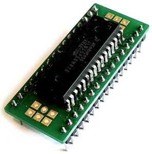
The key hardware components are a 32-pin mc68HC908JL8 MCU mounted on on a DIP adapter and a SiMON6800 PCB. Our kit also included an oscillator, USB serial adapter, headers, and some fixings .
MCU
SiMON6800 PCB
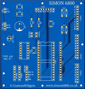
PCB Layout
The size of the PCB is approximately 89mm wide x 95mm high
Most of the header positions are clearly marked, so their function should be clear. Contact us if you have questions.
The less obvious positions are:
- EXT, this is a 1:1 pin mapping to the right-hand row of MCU pins. This facilitates an wider adapter board for a different MCU which we may offer, or you can make.
- The OSC can accommodate either a 14-pin OR 8-pin 9.8304mhz oscillator
- SER-IN is the USB serial port header, which maps 1:1 to the SERIAL pads. Neither of these two header are connected to anything, except themselves. The MCU pins 13 and 14 are used for serial communications (fixed at 9600 baud), as detailed in the SCI section of the NXP data sheet
- The Pin-MAP pads is to allow you to map a USB Serial adapter to the connections used by the PCB (on the Pin-MAP pads). You connect GND, 5V, TX and RX from the SERIAL pads to the appropriate Pin-MAP pads. This allow the use of different USB Serial adapters having different pin-outs
- PWR-SEL allow the selection of whichever power is to be used for the PCB – either the USB 5V or an external 5V on the PWR pads. Use ONLY a 2-pin header jumper and do not connect the 5V lines together
- RST and INT are positions for buttons
- C5 is the MCU decoupling capacitor
- The 10K resistor and C4 (0.1uf) comprises the reset circuit
- R3 is the INT pull up
- CLKEXT allows the connection of the Crystal Oscillator output to the CTRL header (not connected as supplied)
- OSC2A6 allows the conection of OSC2 to the PortA6 header (this is not connected as supplied. Use of an external oscillator means PTA6 is not available)
- C1, C2, C3 are optional decoupling and smoothing capacitors (not supplied)
- The MCU Pin Mapping is detailed in the NXP data sheet